
The simplest way to diagram and collaborate. Take a look at some of the great features.

Simple Yet Powerful
Create shapes and connectors in a single interaction. Position shapes precisely with drag-and-drop.

Diagrams in MS Products
Embed interactive diagrams in MS applications. Word, PowerPoint, OneNote and Outlook are supported.

Import Visio Files
Switch from Visio to Visual Paradigm now to enjoy a sleeker, more intuitive diagramming solution.

Multi-Export Options
Export diagrams in many image formats and as PNG, JPG, GIF, SVG for reporting, publishing and presentation.

Professional Templates
Create professional diagrams using a variety of templates. 2000’s of ready-to-use templates are available.

Collaborate with Anyone
Seamless collaboration for teams and clients. Add comments to review and discuss design ideas.
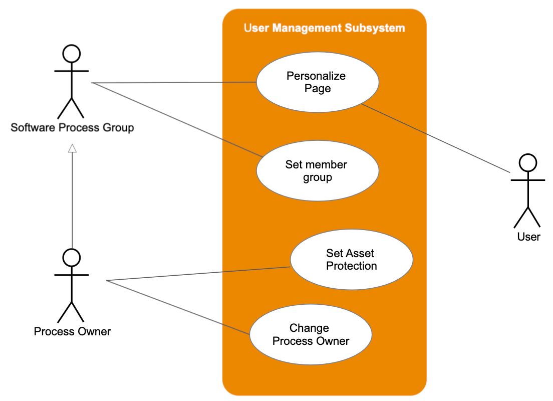
Анализ предметной области и проектирование являются первыми этапами в жизненном цикле создания программного решения. Одним из результатов этого этапа является диаграмма вариантов использования (Use Case), описывающая основные группы пользователей системы и варианты ее использования.
Предметная область — это часть реального мира, данные и особенности которой будут отражены в разрабатываемом программном решении. Например, в качестве предметной области можно выбрать бухгалтерию какого-либо предприятия, отдел кадров, банк, магазин и т. д. Предметная область бесконечна и содержит как важные понятия и данные, так и малозначащие или вообще ничего не значащие данные. Так, если в качестве предметной области выбрать учет товаров на складе, то понятия «накладная» и «счет-фактура» являются важными, а то, что сотрудница, принимающая накладные, имеет двоих детей — это для учета товаров неважно. Однако с точки зрения отдела кадров данные о наличии детей являются важными. Таким образом, значимость данных зависит от выбора предметной области.
В рамках курса для демонстрации основных модулей было выбрано туристическое агентство. Давайте проанализируем вводное описание и определим данные, которые действительно необходимы для нашей системы. Перед вами описание предметной области (важные данные мы будем отмечать маркерами: красным — роль пользователя, желтым — важные действия, которые могут совершать пользователи)
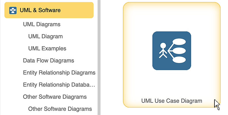
Use Case Diagram
PayPal
Credit
Payment
Identity
<<Service>>
Service
Provider
Authentication
Online Shopping
<<include>>
<<include>>
View Items
Make
Purchase
Checkout
Client
Register
Registered
Customer
Customer
New
Customer
Web
With SmartDraw, You Can Create More than 70 Types of Diagrams, Charts, and Visuals
Learn More
What is a Use Case Diagram?
A use case diagram is a dynamic or behavior diagram in UML. Use case diagrams model the functionality of a system using actors and use cases. Use cases are a set of actions, services, and functions that the system needs to perform. In this context, a «system» is something being developed or operated, such as a web site. The «actors» are people or entities operating under defined roles within the system.
Back to top
Why Make Use Case Diagrams?
Use case diagrams are valuable for visualizing the functional requirements of a system that will translate into design choices and development priorities.
They also help identify any internal or external factors that may influence the system and should be taken into consideration.
They provide a good high level analysis from outside the system. Use case diagrams specify how the system interacts with actors without worrying about the details of how that functionality is implemented.
Back to top
Basic Use Case Diagram Symbols and Notations
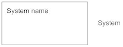
System
Draw your system’s boundaries using a rectangle that contains use cases. Place actors outside the system’s boundaries.
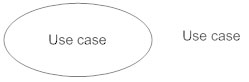
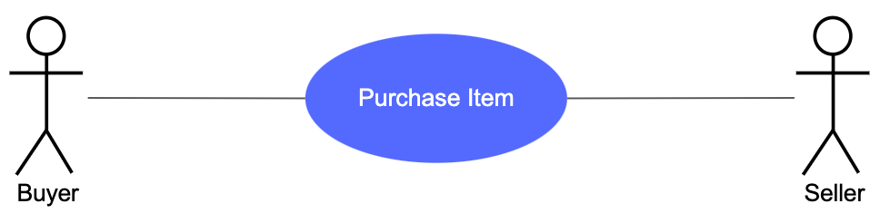
Use Case
Draw use cases using ovals. Label the ovals with verbs that represent the system’s functions.
Actors
Actors are the users of a system. When one system is the actor of another system, label the actor system with the actor stereotype.

Relationships
Illustrate relationships between an actor and a use case with a simple line. For relationships among use cases, use arrows labeled either «uses» or «extends.» A «uses» relationship indicates that one use case is needed by another in order to perform a task. An «extends» relationship indicates alternative options under a certain use case.

Use Case Diagram Tool Tutorial
Start with one of SmartDraw’s blank UML diagram templates or an included use case diagram example. You can quickly add shapes and users and connect them. To add text, just click and type.
Back to top
Tips for UML Use Case Diagrams
When thinking of use cases, think of the end goal of a user. They don’t want to «login» or «sign up.» That’s not a use case. The use case is more like «make a purchase.»
Actors don’t have names. They’re not «Bob.» They represent the role of someone interacting with the system.
Keep your names short and the size of your use cases consistent for a professional look.
For a detailed implementation of a user’s goal use a sequence diagram.
Back to top
Use Case Diagram and Other UML Examples
The best way to understand use case diagrams is to look at some examples of use case diagrams.
Click on any of these UML diagrams included in SmartDraw and edit them:
Get started with Venngage’s online use case diagram and create your own in only a few minutes. 40,000+ businesses use Venngage to create professional diagrams!
Trusted by
![]()
![]()


It allows visualizing the system structure and possible users interactions that would need to be considered for its application.

Supports visual learners to catch potential issues or conflicts within the system and how to possibly address them.

A Use Case Diagram will allow better communication and understanding between peers into how the system is being set up.

This type of diagram will also support process documentation, as various iterations of the same system is being developed and shared across the board.
1
Sign up for Venngage using your email, Gmail or Facebook account.
2
Select one of our use case diagram examples to start with. We’ve got plenty of templates to choose from, and are frequently adding more.
4
Customize your use case diagram by switching up the fonts and colors.
5
Download your completed use case diagram in high-def PNG or PDF format.


With an extensive background in data visualization, our graphic design experts have built an entire library of templates for you to choose from.

Simply type, drag, and drop in your actors and use cases. Take advantage of the icons too to let your creative self go!

Our no-fuss design editor makes it incredibly easy to customize your use case diagram template.

Venngage offers thousands of free icons. These could be perfect to represent actors and systems!

You can save your use case diagram for online presentations or print, whichever you prefer.

Collaborate with your team when using Venngage. Create, share comments and feedback in real-time!
What is a Use Case Diagram?
A use case diagram is the visualization of a system structure and the possible user interactions with it. This type of diagram can exemplify various types of use cases and different types of interactions.
When to apply Use Case Diagrams?
Applications can vary, but the main ones are: to visually represent a system goal and possible interventions by external or internal factors, to define and organize different reactions to upcoming problems, to specify the context of a system application and to model the basic flow of the system.
What are the main components of a Use Case Diagram?
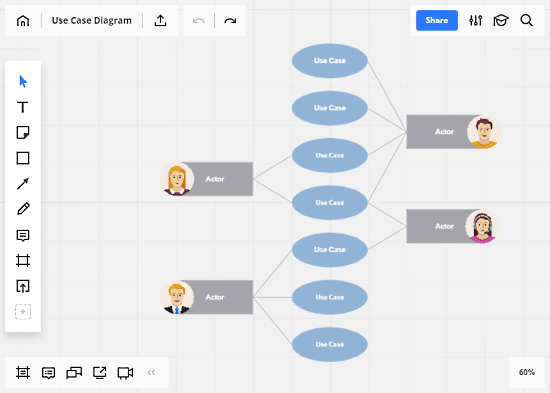
A use case diagram normally contains circles or ellipses that represent the use cases and actors that are represented by icons or stick figures.
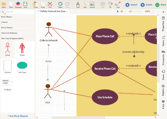
This article covers 5 free websites to draw Use Case Diagram online. A Use Case Diagram aka behavior diagram represents a user’s interaction with a system and shows the relationship between the user and the different use cases in which the user is involved. It generally has Actors (represents users) and various Use Cases and provides some valuable results of the system.
With these websites, you can easily draw Use Case Diagram in few simple steps. They offer various shapes for Use Case Diagram, so all you have to do is add names, actions, and relationships between them. So, let’s dive in the list and see what these websites have to offer.
Related: 5 Free Websites To Draw Activity Diagram Online
Draw.io
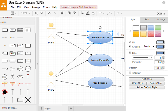
Draw.io is an online diagram editor that offers a variety of features and tools to help you draw any sort of database modeling diagram. You can easily draw Use Case Diagram with Draw.io; the only knowledge you need for that is the understanding of Use Case Diagram. Draw.io features a wide collection of UML shapes and objects which together ease up the process of drawing. All you have to do is drag the objects to the editor and draw relationships between them. You can style your diagram with colors and visual tweaks, and can also change the font and alignment as per your needs.
Apart from the drawing, Draw.io offers a wide range of functionality to make the overall process very efficient for you. It lets you import databases, images, and diagrams, not only from the local storage but also from cloud storage. Same holds up for the export as well. You can export your diagram(s) in various formats to your local as well as cloud storage.
Draw Use Case Diagram online with Draw.io here.
LucidChart
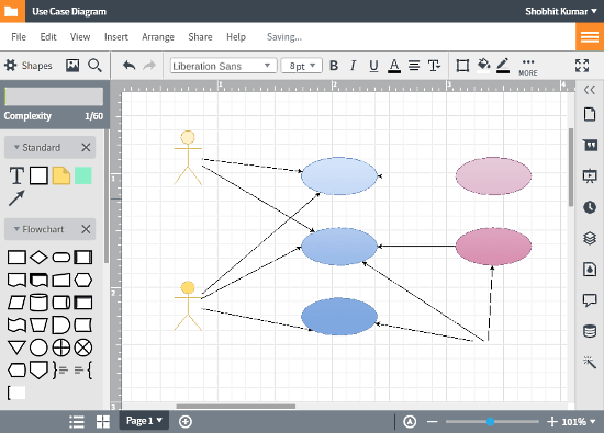
LucidChart is a fully-fledged online diagram editor where you can easily draw any type of database modeling diagrams. This editor offers a variety of shapes for UML Use Case Diagram which are just a single click away. All these shapes make the overall drawing process very easy and give an effective boost to your productivity.
Apart from the drawing process, it has a publishing tool that helps you share your design with others. This tool can also generate HTML code to embed your diagram on the web pages.
Try LucidChart online diagram editor here.
Creately
Creately is another online diagram editor web application that is absolutely free. Like others, it also has a dedicated set of shapes for Use Case Diagrams. You can use them in your diagram simply by drag and drop, which makes the whole process really easy and fast. Apart from that, Creately has a vast template library, where you can find various types of Use Case Diagrams for different domains. With Creately, you can generate interactive diagrams along with the HTML code to embed them on the web pages.
Draw Use Case Diagram online with Creately here.
RealTimeBoard
RealTimeBoard is a web application for cross-functional teams collaboration. It does not offer as much as others do, but you can easily draw a simple Use Case Diagram here. It has Actors and Use Cases which are the two essential parts of a Use Case Diagram. The shapes here has a different design than others which seems to be inspired by the popular Material design. Along with all the basic export options, you can convert your diagram as database to a CSV spreadsheet.
Give RealTimeBoard a try here.
yUML
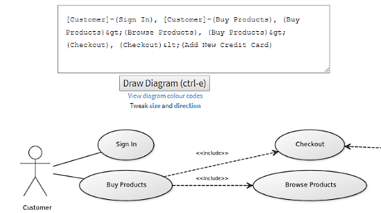
This web tool does not require any drawing tools to draw Use Case Diagram online. It uses UML programming to plot Use Case Diagram. This is not a confusing typical programming; there is a tiny simple syntax for each type object, for example, [] for actor () for the use case, – for relation, > for include, and < for exclude. If you still feel confused, you can see samples and syntax here for easy guidance. You can also add color to the objects by mentioning the color syntax {bg:yellow} at the end of the objects.
Apart from that, you can tweak the size and direction of your diagram. This tool also offers 3 design themes which change the color and font in the diagram. In the end, it generates permalinks to your diagram which you can use to share your work. You can also save it online by creating a yUML account which is absolutely free.
Plot Use Case Diagram online with yUML here.
Wrap Up
These websites have friendly user interfaces and are very efficient for drawing Use Case Diagram online. Try each of them yourself and share your thoughts with us in the comments.
Hint: If you’re sharing with someone in Slack, WhatsApp or whatever, pick .jpg so that the image has a solid white background.
On Twitter, Email, Slack or Facebook
As a link back to this site for editing
For when you want to come back and continue editing this diagram.
As a vector .svg image
Great for editing in vector tools or embedding on the web.
As a .png image
Nice for blogs, wikis or email. Transparent background.
As a .pdf document
Great for printing. Infinite zoom.
As a .jpg image
Solid background. Plays nicer with some desktop tools.
As a .json file
To programmatically save metadata.
Недавно мы разбирали, как построить UML-диаграмму последовательности на примере проведения платежей в интернет-магазине с помощью защищенного банковского шлюза. В продолжение этого кейса, сегодня построим UML-диаграммы вариантов использования, классов и состояний для системы оплаты курса с применением промокода на скидку.
Границы системы, акторы и варианты использования: что такое диаграмма Use Case
Проектируя программную систему, аналитик прежде всего отвечает на вопрос, что она должна делать, т.е. какие возможности представлять для разных пользователей. Для описания таких вариантов использования в UML есть одноименная диаграмма – Use Case. Она позволяет наглядно показать границы системы и ее функции, сгруппированные по контексту – прецеденты. При том, что каждый прецедент фактически отражает одно или сразу несколько функциональных требований, UML-диаграмма Use Case и одноименная форма представления требований – это разные вещи, хоть и связанные между собой. Подробнее об этом мы рассказывали в отдельной статье.
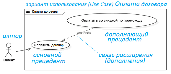
В качестве иллюстративного примера рассмотрим систему онлайн-оплаты учебного курса. Пользователем этой системы является клиент. В терминологии UML он будет называться актор – сущность за пределами системы, которая взаимодействует с ней. На UML-диаграмме Use Case он изображается в виде человечка. Актору «Клиент» доступен основной вариант использования – «Оплатить договор» (на проведение обучающего курса по бизнес-анализу). Расширением этого варианта использования является «Оплатить со скидкой по промокоду», который уменьшает сумму платежа. Этот вариант использования является опциональным и расширяет основной, поэтому он будет связан с основным через связь extend, которая выглядит как пунктирная стрелочка с соответствующей надписью.
Далее следует детализировать, как именно выполняется процесс оплаты, раскрыв прецедент со схемы Use Case на UML-диаграмме последовательности. Однако, чтобы сделать это с привязкой к внутренним сущностям нашей программной системы, классам, следует сперва описать их на UML-диаграмме классов. Как это сделать, мы рассмотрим далее.
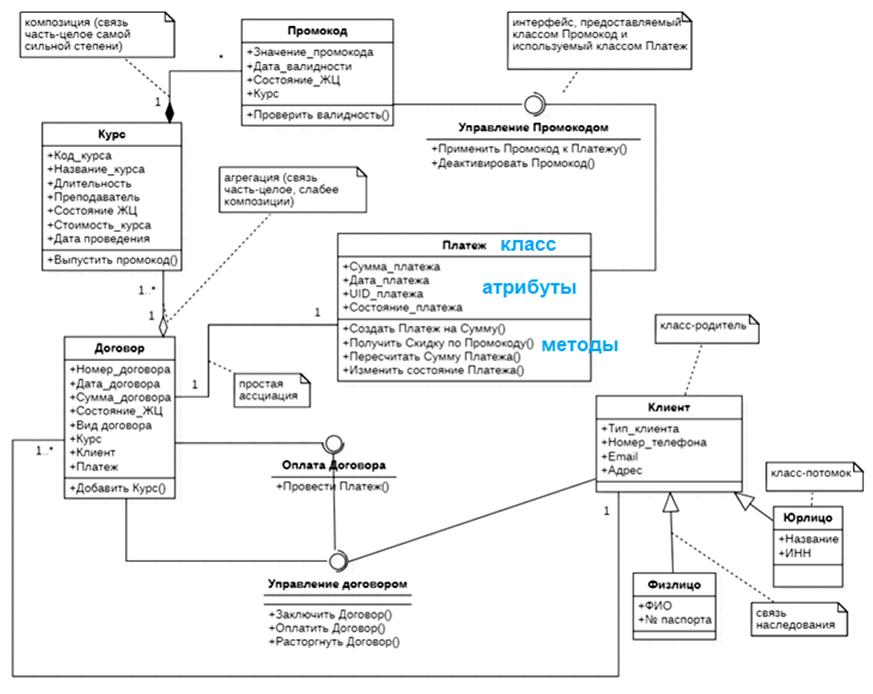
Ликбез по ООП или как построить UML-диаграмму классов
UML соответствует объектно-ориентированной парадигме программирования (ООП), ключевым понятием которой является класс. Класс – это абстракция сущностей с одинаковыми свойствами (атрибутами, полями) и поведением (методами, функциями). Классы могут быть связаны друг с другом через наследование и ассоциации. При наследовании класс-потомки имеют (наследуют) атрибуты и методы класса-родителя, а также свои собственные. А конкретные значения этих атрибутов задаются в реализации классов в виде их отдельных экземпляров, называемых объектами. Например, ООО «Рога и Копыта» и Иванов Иван Иваныч – это конкретные реализации классов «Юрлицо» и «Физлицо» соответственно. В частности, у объекта класса Физлицо есть поля с паспортными данными (ФИО и № паспорта), а у юрлица обязательно должны быть название и ИНН. При этом оба этих класса наследуют от родителя (Класс «Клиент») общие для них атрибуты (тип, номер телефона, email и адрес).
Ассоциация означает логическую связь между объектами разных классов. Например, договор на обучение связан с курсом. Поскольку в договоре нужно обязательно указать курс, эти классы будут связаны не простой ассоциацией, а ее более сложным вариантом – агрегацией. В этом случае у класса, который является целым, появится значок в виде незакрашенного ромбика. Если связь между объектами разных классов настолько сильная, что при уничтожении целого, уничтожаются и его части, ромбик будет закрашенным. Такая связь называется композицией и является самым сильным вариантом ассоциации. Можно также указать кратность связи, к примеру, в 1-м договоре на обучение могут быть указаны сразу несколько курсов. При этом над концами связи отобразятся мультипликаторы, обозначающие ее кратность.
UML для бизнес-аналитика: основы ООП и разработка моделей
Код курса
BUML
Ближайшая дата курса
23 марта, 2023
Длительность обучения
8 ак.часов
Стоимость обучения
15 000 руб.
Таким образом, в нашей системе интернет-оплаты договора с применением промокода по конкретному курсу будут следующие классы:
- Клиент – абстрактный класс-родитель для классов «Юрлицо» и «Физлицо»;
- Физлицо;
- Юрлицо;
- Договор;
- Курс;
- Промокод;
- Платеж.
Объекты разных классов могут взаимодействовать друг с другом через интерфейсы. В ООП интерфейс можно рассматривать как класс без атрибутов, но с методами, которые описывают поведение объекта класса, реализующего этот интерфейс, отвечая за предоставляемые функции. Это позволяет обеспечить один из ключевых принципов ООП – полиморфизм, чтобы унифицировать методы работы с разными объектами, вне зависимости от их типа и внутренней структуры. Например, класс «Промокод» предоставляет интерфейс «Управление промокодом», который используют объекты класса «Платеж». В результате, UML-диаграмма классов для нашего примера примет следующий вид.
Теперь, имея диаграмму классов, которая на концептуальном уровне описывает доменную область проектируемой системы, можно показать, как объекты разных классов взаимодействуют друг с другом на UML-диаграмме последовательности (Sequence).
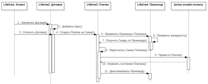
Чтобы упростить рассмотрение основ ООП и базовых концепций UML, эта диаграмма последовательности не полностью отражает весь процесс интернет-оплаты через банковский шлюз. Как это происходит в реальности, мы рассматриваем здесь.
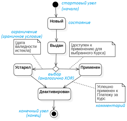
А в заключение покажем, как выглядит жизненный цикл объектов класса «Промокод» с помощью UML-диаграммы состояний (StateChart или State Machine). На мой взгляд, из всех UML-диаграмм она самая простая и понятная без дополнительных объяснений. Начиная со стартового события, объект последовательно проходит разные стадии жизненного цикла, меняя свое состояние в зависимости от некоторых условий.
Как описать архитектурные аспекты проектируемой информационной системы с помощью UML, читайте в нашей новой статье.
Проверить свои знания UML вы можете прямо на нашем сайте, выполнив бесплатный интерактивный тест.
Открытый тест по UML: основы бизнес-анализа для начинающих
А научиться самостоятельно разрабатывать эти и другие UML-диаграммы вам поможет специализированный курс «UML для бизнес-аналитиков». Только практика на реальных примерах. После 8-часового интенсива вы сможете дополнять текстовые схемы представления требований User Story и Use Case UML-диаграммами вариантов использования и детализировать их далее в диаграммы деятельности, последовательности и состояний, чтобы наглядно объяснить разработчикам, что именно должна делать программная система.